Please first login if you wish to upgrade to use this programme! Register Now
- Chassis Dyno Design Programme - Inertia Type
- Example 1 - Solid Roller
- Example 2 - Hollow Roller
- Example 3 - Hollow/Solid Roller with Flywheel
Chassis Dyno Design Programme - Inertia Type
Top
Example - Solid Roller
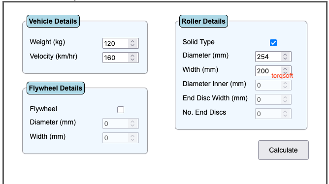
In order to design a Chassis Dyno of the Solid Roller Inertia type, first enter the design weight and velocity into the Vehicle details box. Next enter the outer diameter of the solid Roller plus an approximate value for the roller width into the roller details box. Ensure that the "Solid Type" checkbox is enabled. Now hit the "calculate" button.
The first line of the calculated output information is the required "Moment of Inertia" for the roller. Further down is the actual "Moment of Inertia" for your input details.
If the actual "MOI" value is lower than the required "MOI" value then increase the width of the roller until the actual and required "MOI" values are approx equal. Similarly, if the actual "MOI" is greater than the required value then simply reduce the width of the roller until the desired "MOI" is achieved.
The program also calculates other important information, including "Rotating mass" and "Safety Factor".
Example - Hollow Roller
Designing a Hollow Roller Chassis Dyno has an important advantage over the Solid Roller Dyno - namely reduced rotating mass. This leads to lower bearing loading for the rotating shaft plus an overall reduced Dyno mass.
Top
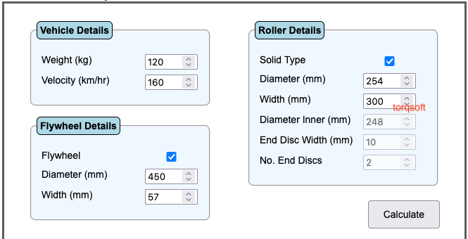
Example - Hollow/Solid Roller with Flywheel
Designing a Chassis Dyno with a "Flywheel" allows the flywheel to have a greater diameter than the Roller Diameter. With this arrangement, the overall rotating mass can be lowered for the same effective inertia
Ensure that the Flywheel checkbox is enable. Next enter values for the flywheel diameter and width. Hit the calculate button. Adjust width of flywheel until the calculated total MOI is approx equal to the calculated required MOI. Notice that the total rotating mass is reduced by over 60% compared to the first example with a solid flywheel.